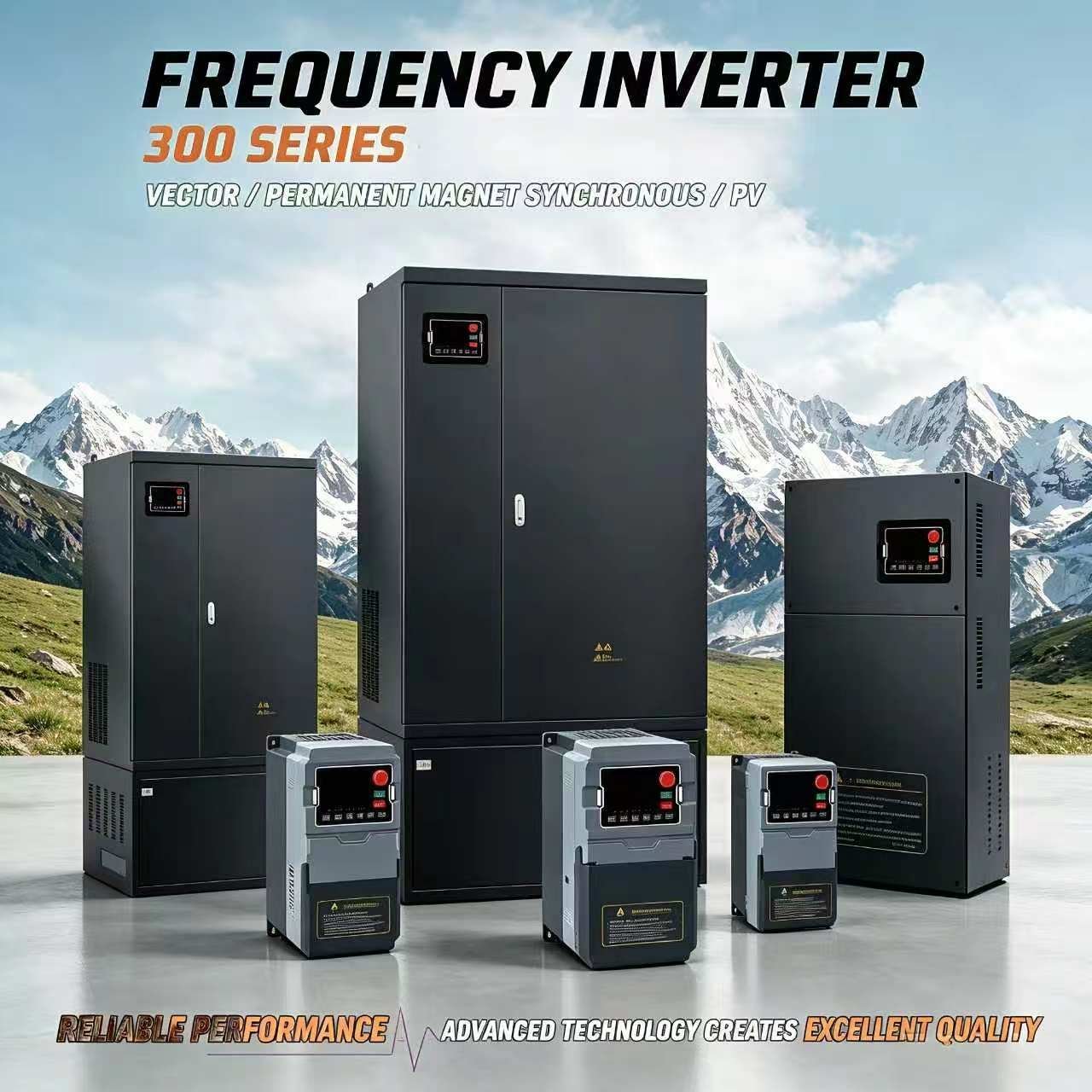
Description
VFD 300 S3 Series – Single Phase 220V Input / Three Phase 380V Output
The VFD 300 S3 Series converts single-phase 220V input to three-phase 380V output, providing a cost-effective solution for running three-phase 380V motors where only single-phase power is available.
Key Features
- Output Frequency: 0-600 Hz
- Overload Capacity: 150% rated current for 1 minute, 180% for 3 seconds
- Control Method: Optimized SVPWM control
- Control Mode: Sensorless vector control
- Frequency Resolution: Digital 0.01Hz; Analog max frequency ×0.025%
- Automatic torque boost: 0.1%-30.0%
- Built-in PID closed-loop control
- Multi-speed operation via built-in PLC
- RS485 communication support
- Comprehensive protection functions
Model Specifications
| Model | Power (kW) | HP | Input Current (A) | Output Current (A) | Enclosure |
|---|---|---|---|---|---|
| 300N-0.75PB-S3 | 0.75 | 1 | 8 | 2.5 | S / Y / D / Z |
| 300N-1.5PB-S3 | 1.5 | 2 | 14 | 3.8 | S / Y / D / Z |
| 300N-2.2PB-S3 | 2.2 | 3 | 23 | 5.1 | S / Y / D / Z |
| 300N-003PB-S3 | 3 | 4 | 27 | 7.2 | S / Y / D / Z |
| 300N-004PB-S3 | 4 | 5 | 39.7 | 9 | S / Y / D / Z |
| 300N-5.5PB-S3 | 5.5 | 7.5 | 41.3 | 13 | S / Y / D / Z |
| 300N-7.5PB-S3 | 7.5 | 10 | 44 | 17 | S / Y / D / Z |
| 300N-011PB-S3 | 11 | 15 | 59 | 25 | S / Y / D / Z |
| 300N-015PB-S3 | 15 | 20 | 75 | 32 | S / Y / D / Z (plastic by default) · iron optional |
| 300N-18.5PB-S3 | 18.5 | 25 | 87 | 37 | Iron enclosure |
Electrical Specifications
| Power Range | Input Voltage | Output Voltage | Output Frequency |
|---|---|---|---|
| 0.75-18.5 kW | Single Phase 220V 50/60Hz | Three Phase 0-380V | 0-600 Hz |
Applications: Industrial machinery, CNC equipment, conveyor systems, and any application requiring three-phase 380V motor operation from single-phase 220V supply.
S3 Series Overview — Single Phase In, Three Phase 380V Out
The S3 series is the single-to-three-phase converter of the 300N range: a single-phase 200–240V input producing a variable three-phase output from 0 to 380V. This is the series to choose when a three-phase 380V motor has to be run from a single-phase 220V supply. Ten models span 0.75 kW to 18.5 kW. Models up to 11 kW use the plastic enclosure, available in four enclosure designs (S / Y / D / Z); the 15 kW model is available with either a plastic or an iron enclosure (plastic standard), and the 18.5 kW model uses the iron enclosure. Output frequency is adjustable up to 600 Hz.
OEM & ODM available. Contact us for pricing and technical support.
Full model list: See all 118 certified 300N models by input/output voltage configuration →
Control Circuit Wiring Diagrams
The following diagrams show the control circuit terminal layout and wiring for each main board type used in the 300 Series. The board type varies by model and power rating.
Main Circuit Terminal Layout
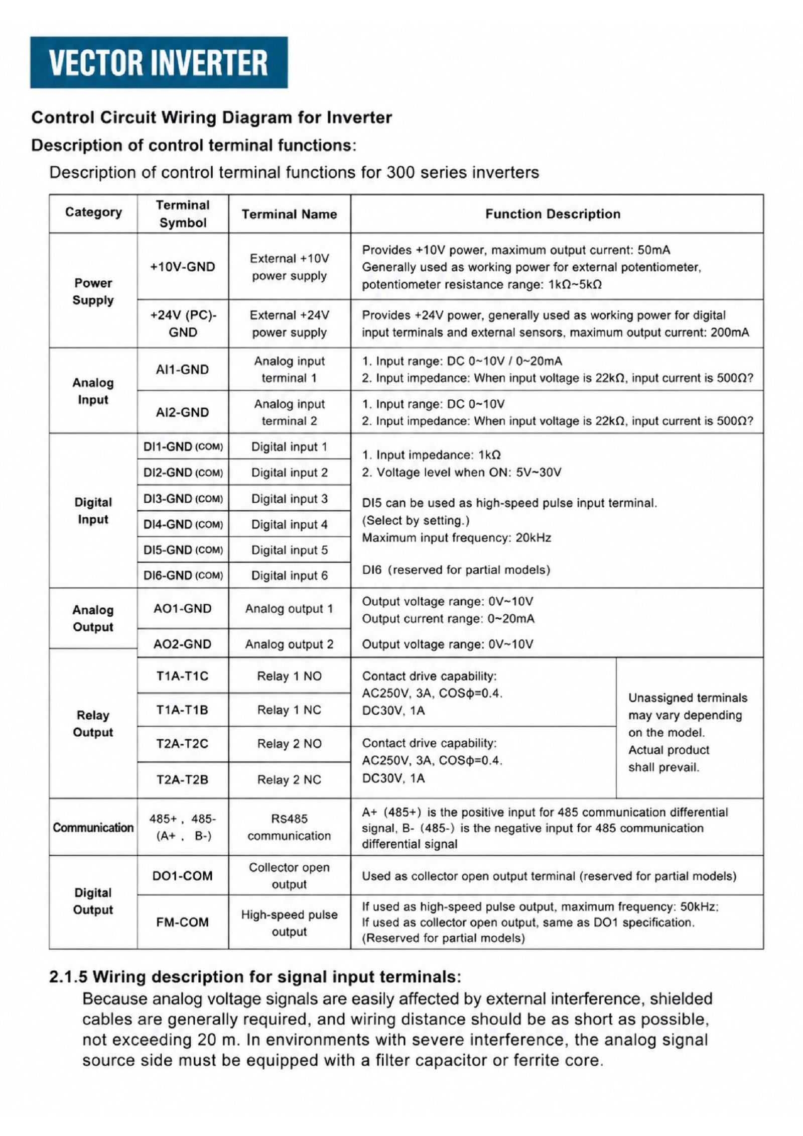
Main Circuit Terminal Layout (R/L1, S/L2, T — PP, PB — U, V, W — G, E)
Tap to open full-size diagram
Control Board Wiring Diagrams
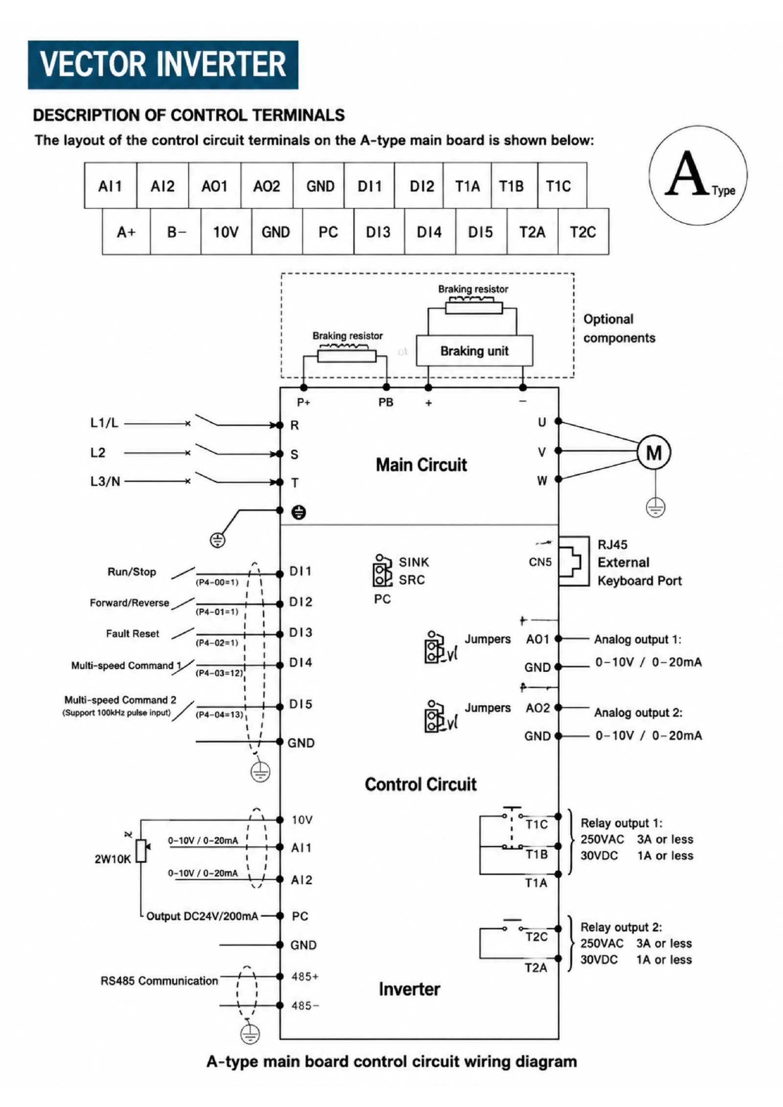
A-Type Main Board Wiring Diagram
Tap to open full-size diagram
Wiring Notes:
- Analog voltage signals require shielded cables; wiring distance should not exceed 20m.
- In severe interference environments, equip analog signal source side with filter capacitor or ferrite core.
- Terminal assignments may vary by model — refer to actual product labeling.
Frequently Asked Questions
What input and output does the 300N S3 series use?
Single-phase 220V (200-240V) 50/60Hz input and three-phase 0-380V output. It is the single-to-three-phase converter of the 300N range: it runs a three-phase 380V motor from a single-phase supply.
Which power ratings are available in the S3 series?
Ten models covering 0.75 kW to 18.5 kW (1 HP to 25 HP), from 300N-0.75PB-S3 up to 300N-18.5PB-S3.
What is the output frequency range?
0-600 Hz, with a digital frequency resolution of 0.01 Hz (analog resolution is max frequency x 0.025%).
What is the overload capacity of the S3 series?
150% of rated current for 1 minute and 180% of rated current for 3 seconds.
Which enclosure options are available?
The 0.75-11 kW models are available in S / Y / D / Z enclosures. The 15 kW model is plastic by default with iron optional, and the 18.5 kW model uses an iron enclosure — as listed in the model table above.
What applications is the S3 series suitable for?
Industrial machinery, CNC equipment, conveyor systems and any application that needs three-phase 380V motor operation from a single-phase 220V supply.

Reviews
There are no reviews yet.