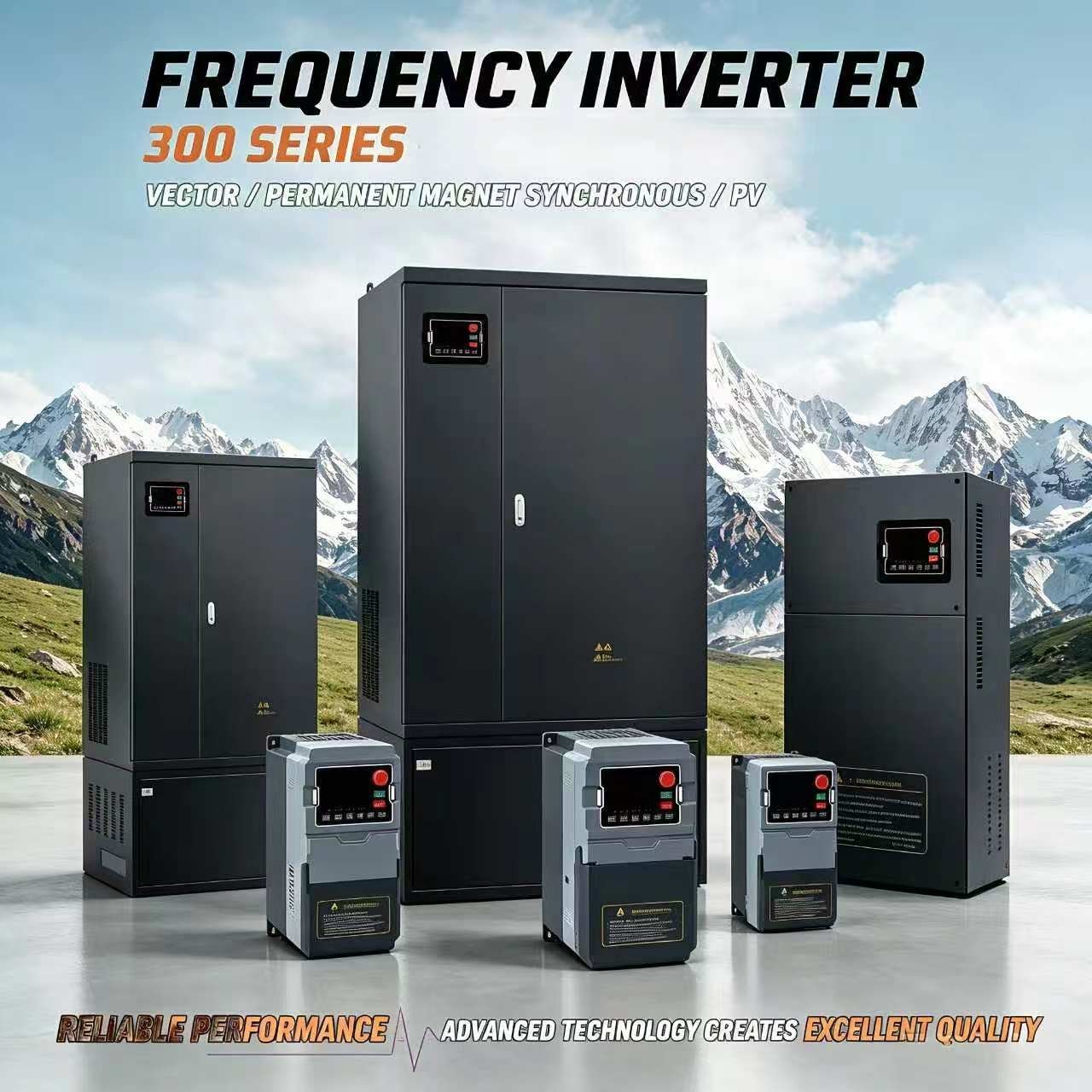
Description
VFD 300 H2 Series – Single Phase 220V Input / Single Phase 220V Output
The VFD 300 H2 Series is a high-performance vector inverter designed for single-phase 220V input and single-phase 220V output applications. Ideal for small motor speed control with advanced SVPWM control technology.
Key Features
- Output Frequency: 0-600 Hz
- Overload Capacity: 150% rated current for 1 minute, 180% for 3 seconds
- Control Method: Optimized SVPWM control
- Control Mode: Sensorless vector control with optimal low-frequency dead zone compensation
- Frequency Resolution: Digital 0.01Hz; Analog max frequency ×0.025%
- Built-in PID closed-loop control
- Multi-speed operation via built-in PLC or control terminals
- RS485 communication support
- 5 programmable digital inputs
- 2 analog inputs (0-20mA, 0-10V)
- 2 relay outputs
- Comprehensive protection: overcurrent, overvoltage, undervoltage, overheat, overload
Model Specifications
| Model | Power (kW) | HP | Input Current (A) | Output Current (A) | Enclosure |
|---|---|---|---|---|---|
| 300N-0.75G-H2 | 0.75 | 1 | 4.5 | 4 | S / Y / D / Z |
| 300N-1.5G-H2 | 1.5 | 2 | 8 | 7 | S / Y / D / Z |
| 300N-2.2G-H2 | 2.2 | 3 | 11 | 9.6 | S / Y / D / Z |
| 300N-003G-H2 | 3 | 4 | 14 | 12 | S / Y / D / Z |
Electrical Specifications
| Power Range | Input Voltage | Output Voltage | Output Frequency |
|---|---|---|---|
| 0.75-3.0 kW | Single Phase 220V 50/60Hz | Single Phase 0-220V | 0-600 Hz |
Applications: CNC machines, small conveyors, packaging equipment, textile machinery, and other single-phase motor control applications.
H2 Series Overview — Single Phase In, Single Phase Out
The H2 series takes a single-phase 200–240V supply and delivers a variable single-phase output from 0 to 240V, so the speed of a single-phase motor can be adjusted instead of running at a fixed speed. Because input and output are both single phase, no phase conversion is involved: this is the series to choose when the load itself runs on a single-phase supply. Four models cover 0.75 kW to 3.0 kW. The 200–240V input window covers both 220V and 240V single-phase supplies, and output frequency is adjustable up to 600 Hz. Models in this series use the plastic enclosure and are available in four enclosure designs (S / Y / D / Z).
OEM & ODM available. Contact us for pricing and technical support.
Full model list: See all 118 certified 300N models by input/output voltage configuration →
Control Circuit Wiring Diagrams
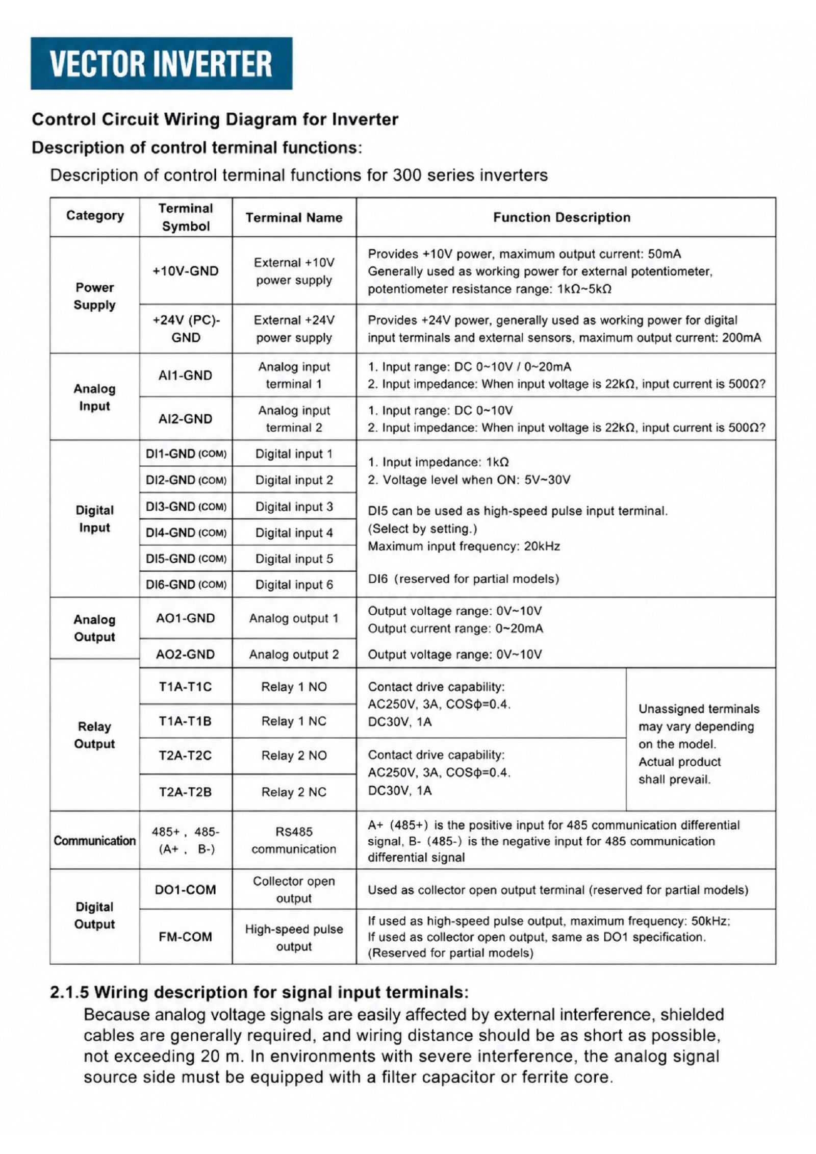
The following diagrams show the control circuit terminal layout and wiring for each main board type used in the 300 Series. The board type varies by model and power rating.
Main Circuit Terminal Layout
Main Circuit Terminal Layout (R/L1, S/L2, T — PP, PB — U, V, W — G, E)
Tap to open full-size diagram
Control Board Wiring Diagrams
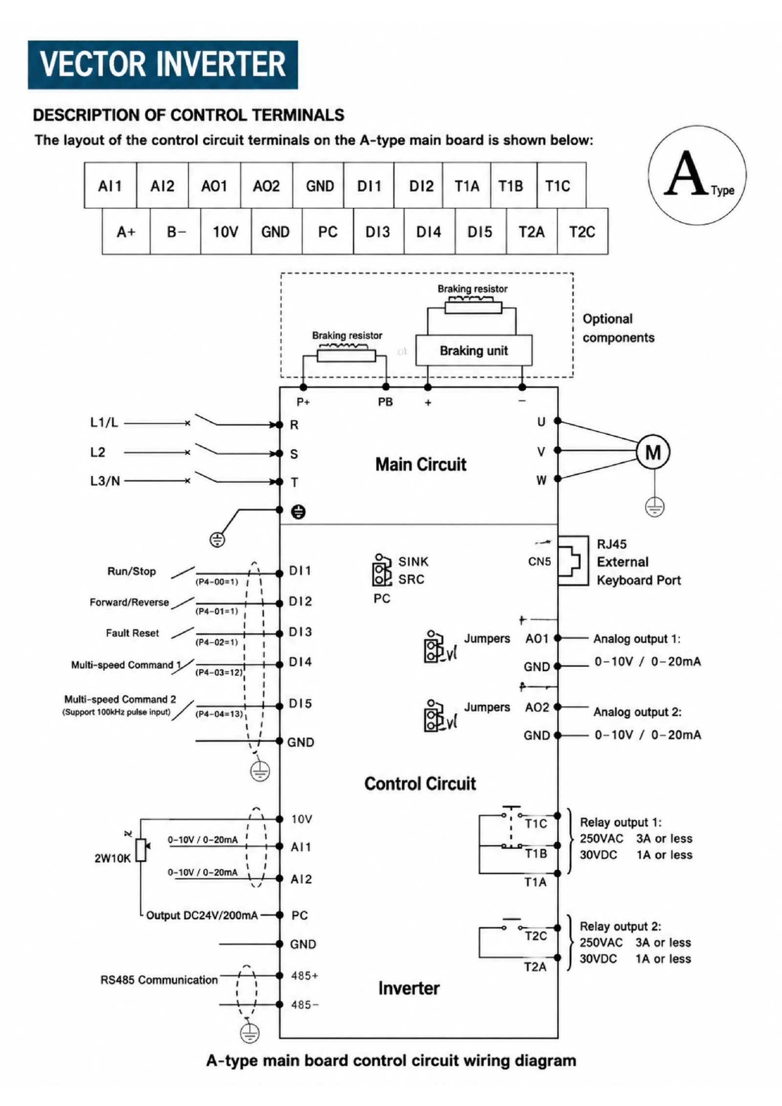
A-Type Main Board Wiring Diagram
Tap to open full-size diagram
Wiring Notes:
- Analog voltage signals require shielded cables; wiring distance should not exceed 20m.
- In severe interference environments, equip analog signal source side with filter capacitor or ferrite core.
- Terminal assignments may vary by model — refer to actual product labeling.
Frequently Asked Questions
What input and output does the 300N H2 series use?
Single-phase 220V (200-240V) input and single-phase 0-220V (0-240V) output, 50/60Hz. Because both input and output are single phase, no phase conversion is involved.
Which power ratings are available in the H2 series?
Four models covering 0.75 kW to 3.0 kW (1 HP to 4 HP): 300N-0.75G-H2, 300N-1.5G-H2, 300N-2.2G-H2 and 300N-003G-H2.
What is the output frequency range?
0-600 Hz, with a digital frequency resolution of 0.01 Hz (analog resolution is max frequency x 0.025%).
What is the overload capacity of the H2 series?
150% of rated current for 1 minute, and 180% of rated current for 3 seconds.
What control method and communication does it support?
Optimized SVPWM control with sensorless vector control and low-frequency dead zone compensation, built-in PID closed-loop control, RS485 communication, 5 programmable digital inputs, 2 analog inputs (0-20mA / 0-10V) and 2 relay outputs.
What applications is the H2 series suitable for?
CNC machines, small conveyors, packaging equipment, textile machinery and other single-phase motor control applications.

Reviews
There are no reviews yet.